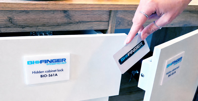
1. General Questions
1.1. What is included in the set without an external panel?
The standard package of the invisible RFID furniture lock includes:
- Electronic RFID furniture lock (main body + latch bolt or strike plate).
- Two RFID proximity cards: 1x Manager card (Admin) and 1x User card.
- Complete screw mounting kit.
Batteries are not included in the set.
1.2. What is included in the set with an external panel?
The package with an external access panel includes:
- Electronic furniture lock body + motorized latch bolt.
- External touch panel for RFID cards and/or PIN code.
- Flexible flat ribbon connecting cable (approx. 10 cm long).
- Two proximity cards: 1x Manager card and 1x User card.
- Complete screw mounting kit.
Batteries are not included in the set.
1.3. Large quantity of RFID locks: card registration before installation
When purchasing multiple invisible electronic furniture locks, we strongly recommend performing the initial setup on a desk prior to mechanical mounting:
- Register a single master Manager card common to all locks across the office or facility.
- Register individual or shared User cards/key fobs to their designated locks while units are accessible on the bench.
1.4. Maximum furniture front thickness (RFID signal range)
Our professional RFID furniture locks are engineered to penetrate wood, MDF, chipboard, plastics, and glass with a thickness of up to 35 mm (depending on the model). This enables fully concealed installation without drilling visible holes through the front of premium cabinetry.
1.5. Does the invisible RFID lock work through a mirror?
No. The lock will not work through a glass mirror due to the conductive aluminum or lead backing film, which attenuates and reflects high-frequency RFID radio waves. For mirrored doors, please use a model fitted with an external wired panel.
1.6. Operating temperature and humidity range (RH)
Professional locks of the BIO-S series are built to operate reliably in demanding environments:
- Operating temperature: -15°C to +65°C (suitable for unheated storage or chalets).
- Relative humidity: 10% to 90% RH (non-condensing).
- Electrostatic discharge (ESD) protection: up to 15KV air discharge and 8KV contact discharge, safeguarding internal microprocessors.
1.7. Compatibility with Unique 125 kHz and HID cards (Dual tags)
Our locks operate on the high-frequency Mifare 13.56 MHz standard. If your company relies on a legacy 125 kHz or HID building access infrastructure, we offer an elegant workaround:
- Self-adhesive RFID stickers (tags): attach directly onto existing company badges, smartphones, or ID holders.
- Dual-carrier integration: allows employees to use their existing badge to open office furniture seamlessly.
1.8. Warranty terms and manufacturer liability
The warranty period for professional BIOFINGER invisible furniture locks from the BIO-S61A, BIO-S80A, BIO-S90A, and BIO-S123A series is 24 months. The economy model BIO-S8080A is covered by a 12-month warranty.
Important! The warranty does not cover:
- Improper installation (specifically mechanical misalignment between the lock body and the latch strike).
- Failure to comply with operating instructions and battery warning protocols.
- Mechanical damage resulting from forced prying if batteries were depleted after persistent warning alarms were ignored.
1.9. Consequences of using the [RESET] button
Pressing the [RESET] button for approximately 2 seconds restores the lock to factory defaults. This triggers two major system alterations:
- Complete memory wipe: all registered administrative Manager cards and User cards are permanently erased.
- Mode reset: the lock reverts to default public mode, losing any prior private mode configuration.
Attention! Configuration order after a reset:
- For BIO-S61A, BIO-S80A, BIO-S90A, BIO-S123A: Step 1: Private Mode ➔ Step 2: Manager Card ➔ Step 3: User Cards.
- For BIO-S8080A: Step 1: Manager Card ➔ Step 2: Private Mode ➔ Step 3: User Cards.
1.10. Colored marker stickers – what are they used for?
The included circular stickers (white, red, blue, yellow) are optional visual markers. They indicate the exact position of the hidden internal antenna on the exterior of the cabinet. Applying them is purely voluntary if an entirely seamless front is preferred.
2. Acoustic and Visual Signals (Alarms)
2.1. Signal guide: meaning of beeps and LED indicators
- Green LED + 1 beep (di): Access granted. Authorized opening with a valid User card.
- Red LED (2x) + 2 beeps (di-di): Access denied. Unregistered or unauthorized card presented.
- Blue LED + 8 double beeps (di-di): Low voltage alarm. Emitted on every opening cycle. Batteries must be replaced immediately (approx. 1,000 operations remain from first trigger).
- Red LED + 5 rapid beeps: Active safety lockout (Locking Protection). Triggered after 5 invalid attempts. The lock freezes for 5 minutes (can be bypassed immediately with a Manager card).
- Continuous tone (diii): Door-ajar alarm. Sounds if the door remains open past 30 seconds (can be toggled using buttons 1 & 2 in private mode).
- LED off: Standby mode with ultra-low current draw.
3. Power Supply of Invisible RFID Furniture Locks
3.1. What to do if the batteries in the furniture lock are completely discharged?
Such a scenario occurs almost exclusively under specific circumstances—such as leaving batteries inside a lock and keeping the cabinet untouched for several years (e.g. 5 years). Only then can batteries reach absolute depletion.
In the event of total discharge, the electronic lock will remain locked.
To regain access without destroying the furniture front, we suggest cutting a clean inspection hole (using a hole saw) in an inconspicuous area of the front or partition. This provides hand access to replace batteries, detach the strike plate, or unbolt the mechanism cleanly.
Important! Under normal, regular operation, complete lockouts never happen if the user does not ignore the acoustic and visual low-battery alarms emitted upon each opening.
3.2. What happens as battery voltage drops? (Safety Mode)
Our locks actively safeguard users from lockout. The safety logic is calibrated to the model and power source:
- For models BIO-S80A, BIO-S8080A, BIO-S90A, BIO-S123A (4× AAA): low voltage alarm sounds below 4.5V. Safety mode triggers at 4.0V.
- For model BIO-S61A (1× CR123A): low voltage alarm sounds below 2.5V. Safety mode triggers at 2.0V.
Once critical voltage (4.0V or 2.0V) is hit, the device enters safety mode: the latch bolt will not engage again. Following the final authorized unlock, it remains permanently open until fresh batteries are installed, securing unimpeded access to assets.
3.3. Can a constant power supply be connected to the lock?
Yes. All BIO-S models can be powered continuously from the mains using a dedicated external 6VDC switching power supply (via a USB Type-C connector), completely eliminating battery maintenance.
3.4. How long do batteries last in an invisible furniture lock?
Standby power draw is under 100µA, while dynamic motorized draw is under 200mA. Under standard usage (10–15 openings/day), high-grade industrial alkaline cells last 10 to 14 months (approx. 15,000 operations).
Critical battery guidelines:
- Use strictly brand-new industrial-grade batteries (e.g., Duracell Procell or Varta Industrial). Retail consumer batteries from discount stores suffer high internal resistance and sudden voltage drops under motor torque.
- Avoid partially used batteries, as they may fail to trigger the 4.5V low-voltage alarm, resulting in unexpected failure.
- Preventive best practice: set a recurring calendar reminder to swap batteries every 6–10 months depending on footfall.
3.5. What batteries are required for the BIO-S80A and BIO-S61A models?
The universal BIO-S80A requires 4× AAA 1.5V alkaline batteries. The compact BIO-S61A requires 1× CR123A 3V lithium battery. Always use premium industrial cells.
3.6. The lock does not turn on and does not respond to proximity cards
Batteries are not included in standard packaging. Ensure that fresh, high-quality batteries have been inserted with correct polarity.
3.7. Can multiple furniture locks be powered from a single central power unit?
Yes. This can be accomplished in two ways:
- Custom DIY wiring: Running two-core cabling (min. 0.75 mm² copper) to a terminal block. Our 6VDC/2A unit stably handles 5 to 10 locks.
- Plug & Play installation: Using our specialized 7-port USB-DC distribution hubs and pre-terminated 1m or 2m power cables for a clean, modular setup.
4. Operating Invisible RFID Locks in Private Mode
4.1. What is the Manager card used for?
The Manager card is the administrative key used exclusively to enroll or wipe User cards. In private mode, the Manager card cannot unlock the cabinet directly (this prevents administrative intrusion). In public mode, it acts as an emergency master key.
4.2. Managing multiple locks with a single Manager card
You do not need independent admin cards for each desk. We strongly advise registering one single Manager card across all locks in an office facility for centralized, friction-free administration.
4.3. Can a single User card open multiple furniture locks?
Yes, a single User card or RFID fob can be authorized on an unlimited number of BIO-S furniture locks.
4.4. Maximum user capacity per lock
Each invisible furniture lock can store up to 30 proximity User cards or tags.
4.5. What to do if the only User card is locked inside?
If the Manager card is accessible outside, simply use it to enroll a fresh, spare User card in seconds, opening the unit non-destructively.
4.6. Integrated door push-to-open system
Yes, all models feature a spring-loaded mechanical plunger that ejects the door or drawer outwards by 5–15 mm upon RFID authorization.
5. Operating Invisible RFID Locks in Public Mode
5.1. Emergency opening procedure in lockers and Manager card limits
In public mode (gyms, shared lockers), any user card locks an open compartment and releases it upon return. The Manager card performs an emergency override. Note: model BIO-S8080A supports 1 Manager card, whereas standard series support up to 10 Manager cards.
6. RFID Card Registration and Programming Diagrams
6.1. Configuring private operating mode
For models: BIO-S61A, BIO-S80A, BIO-S90A, BIO-S123A
Press button [3]
for 2 sec.
➔
2 beeps
+ Green LED
➔
PRIVATE MODE
CONFIGURED
For model: BIO-S8080A
Press button [1]
3 times
➔
3 beeps
+ Blue LED
➔
Present Manager
card twice
➔
PRIVATE MODE
CONFIGURED
6.2. Registering the administrative Manager Card
Press button [1]
for 2 sec.
➔
Green LED
flashes
➔
Present new
RFID card
➔
MANAGER CARD
SAVED
6.3. Registering User Cards
Present MANAGER
card once
➔
Green LED
flashes
➔
Present new
USER card
➔
USER CARD
SAVED
7. Installer's Guide – Practical Mounting Tips
7.1. Stage 0: Recommended tools and auxiliary materials
- Cordless drill with bits and a thin 2 mm pilot drill bit.
- Center punch or long nail to mark screw centers precisely.
- Vernier caliper or measuring tape for precise axial alignment.
- Spirit level for true horizontal or vertical alignment.
- Double-sided foam mounting tape for trial positioning before drilling.
- Isopropyl alcohol (IPA) to degrease surfaces for temporary tape adhesion.
7.2. Stage 1: Dry run configuration and desk testing
Always verify full functional operation on the bench before drilling into custom millwork. Ensure the motor fires, the plunger ejects, and all user credentials cycle smoothly.
7.3. Stage 2: Drawer installation (Centering and latch alignment)
- Position the main lock body centrally along the drawer's centerline to balance plunger push forces.
- Both lock body and latch strike can be oriented vertically or horizontally.
- Crucial rule: always perform dry test closures with batteries active inside so you can reopen the lock via card without prying components off.
7.4. Stage 3: Hinged cabinet doors and display cases
Maintain a 1 to 2 mm clearance gap. This technical tolerance allows users to slightly press the door inward to relieve latch tension when presenting the RFID credential.
7.5. Stage 4: Technical clearance and stall current prevention
- Emergency service port: Consider drilling a hidden 8 mm port to allow emergency 6VDC auxiliary power connection if needed.
- Zero friction rule: Ensure the bolt enters the catch cavity with zero friction. Drag or mechanical binding causes motor current to spike from 220mA to 350mA (stall current), cutting battery lifespan in half.