


BIO-S61A
- Install brand-new CR123A Lithium battery: Use exclusively brand-new 3V CR123A lithium primary cells of INDUSTRIAL grade (e.g., Panasonic Industrial, Varta CR123A, Duracell Ultra). Never use rechargeable cells or depleted batteries.
- Program and test all credentials prior to mounting: Please ensure that the lock operates properly, and that all credentials (Manager Card and User Cards) are configured, tested, and verified at least 3 times on an open drawer/door before physically securing the lock body and latching the furniture!
- Understand the Reset consequences before pressing RESET: Before pressing the Reset button on the lock body, carefully read Section 7 to understand the factory reset behavior (all cards will be deleted and the lock restores its factory default Public Mode)!
Table of Contents
-
6. Operations & Mode Configuration
- 6.1 Private Mode (Home, Office, Personal Drawers)
- • Registering New Manager Card Manager
- • Registering New User Card(s) (Up to 30) User
- • Registering Delete Card (Batch Clear)
- 6.2 Public Mode (Gyms, Spa, Shared Lockers)
- • Registering New Manager Card Manager
- • Registering New User Card User
- • Registering Delete Card (Clear Locker)
- 6.3 Limited Public Mode (Daytime Open)
- • Registering New Manager Card Manager
- • Registering New User Card User
- • Registering Delete Card
- 7. Reset Lock (Restore Factory Defaults / Public Mode)
- 8. Essential Operational Guidelines & Best Practices
1. Relative Products & Accessories
The BIO-S61A ultra-compact lock body is engineered specifically for concealed installation in small drawers, desk pedestals, file cabinets, and narrow spaces where standard-sized locks cannot fit. In addition, the lock body features an integrated expansion socket compatible with optional external wired accessory panels (Touch Code Panels B, C, D, E, 64RP as well as Proximity/Biometric Panels F, G, 64RF, 36SF, 51SF).
2. Hardware Overview & Components
Standard Set Contents (Included in Each Package):
-
Electronic RFID Ultra-Compact Lock: Lock Body + Compact Spring-Loaded Strike Hook
※ Standard factory configuration: each lock is pre-programmed out-of-the-box to operate in Private Mode. -
Two Pre-Configured Proximity RFID Credentials (13.56 MHz Mifare):
- 1× Manager Proximity Card: Administrative programming key
- 1× User Proximity Card: Operational credential for daily unlocking
- Complete Fasteners Set: Complete set of hardened mounting screws for quick installation in wooden, MDF, or metal furniture.
2.1 Lock Body Specification
Material: High-impact ABS polymer shell.
Dimensions: Ultra-compact 61 × 61 × 22 mm.
2.2 Compact Strike Hook
Designed for versatile installation in small drawers and cabinet doors:
- Compact Strike Hook: Dimensions 60 × 24 × 16.7 mm with a 46 mm mounting screw pitch. Engineered for vertical or horizontal drawer faceplates.
2.3 Proximity Credentials (Cards, Fobs, Bands)
Diverse form factors of 13.56 MHz Mifare RFID credentials supported: waterproof silicone wristbands, robust ABS key fobs (teardrop/oval), ISO rectangular cards, and adhesive tokens.
2.4 Fasteners & Screws Specification
Corrosion-resistant, hardened installation screws provided for diverse cabinet substrates (hardwood, MDF, MFC, metal) and varying front drawer thicknesses.
2.5 External Power Interface & Battery Rules
Equipped with an integrated emergency backup port. Compatible with external battery boxes and emergency power adaptors to supply temporary DC power if internal battery is exhausted.
The BIO-S61A operates on a single 3V CR123A Lithium primary cell. To guarantee maximum read distance through timber and prevent mechanism stalling, only and exclusively install brand-new, fresh 3.0V CR123A Lithium batteries from a professional manufacturer – INDUSTRIAL Grade (e.g., Panasonic Industrial CR123A, Varta CR123A, Duracell Ultra/Procell CR123A).
STRICTLY PROHIBITED:
• NO 3.7V rechargeable 16340/RCR123A batteries: Voltage above 3.3V can permanently damage the internal 3V microchip.
• NO partially discharged or expired cells: Always install brand-new lithium cells with a verified voltage of ≥ 3.0V.
3. Product Installation Dimensions
Lock Body Dimensions (Ultra-Compact)
- Outer dimensions: 61 mm × 61 mm × 22 mm.
- Mounting screw holes: 4 × Ø4.5 mm holes arranged in a 46.5 mm × 46.5 mm square pitch.
- Edge margins: 11.5 mm / 17.5 mm from hole centers to casing edges.
- Latch receptor: Centered at 11.5 mm from top face.
Compact Strike Hook Dimensions
- Outer dimensions: 60 mm (L) × 24 mm (W) × 16.7 mm (H).
- Mounting screw holes: 2 × Ø4.4 mm holes with 46 mm center-to-center pitch.
- Spring-loaded deadbolt pin extension: 24 mm center spacing.
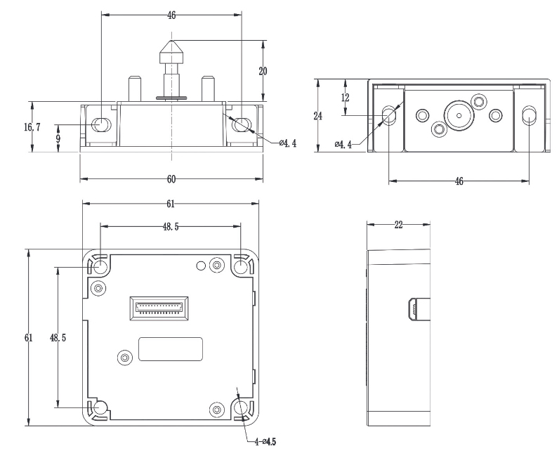
4. Installation Drawings & Drawer Assembly
The ultra-compact lock body mounts flush against the internal cabinet partition wall, drawer runner divider, or shelf using 4× screws. The compact strike hook mounts onto the inner face of the drawer front using 2× screws. The spring-loaded locking latch bolt engages seamlessly into the lock body receptor slot. Ensure accurate alignment before securing fasteners firmly.
5. Operational Parameters & Master Matrix
5.1 Technical Parameters
| Housing Construction | High-impact ABS for lock body shell; Acrylic & PC for optional panels |
| Current Consumption |
Static standby consumption: < 50 μA @ 3V Operating load current: < 200 mA Locked-rotor current: < 350 mA |
| Operating Voltage & Battery Lifetime |
DC 3V (1 × CR123A 3.0V Lithium INDUSTRIAL Cell) Operating voltage range: 2.1V to 3.3V. Estimated operational battery life: 6–12 months (depending on daily cycles). |
| Low Voltage Alarm Thresholds |
Pre-alarm threshold: 2.5V ± 0.1V (Blue LED + acoustic warning) Ultimate critical cutoff: 2.1V (failsafe final unlock / no re-lock) |
| Environmental Tolerance | Operating temperature: -15°C to +65°C Operating humidity: 10% to 90% RH (non-condensing) |
| Electrostatic Protection (ESD) | Air discharge: 15 kV | Direct contact discharge: 8 kV |
5.2 Master Alarm & Notification Signal Matrix
The BIO-S61A integrates an acoustic buzzer and multi-state LED indicator to communicate system statuses, security lockdowns, and battery thresholds:
| Status / Trigger Event | Optical (LED) | Acoustic (Buzzer) | System State & Required Action |
|---|---|---|---|
| Valid Card Presented | Green (1× flash) | 1× short di | Authorized unlock. Motorized latch bolt retracts. |
| Unauthorized Card | Red (2× flashes) | 2× short di di | Access denied. Credential is not registered in system memory. |
| Low Voltage Warning (< 2.5V) | Blue (steady flash) | Double beep di di on each unlock | LOW BATTERY ALERT (< 2.5V ± 0.1V): Warning on every opening. Lock remains functional for ~1,000 cycles, but fresh 3V CR123A Lithium battery must be installed promptly. |
| Critical Voltage Failsafe (< 2.1V) | Blue (continuous) | Periodic warning tone | ANTI-ENTRAPMENT FAILSAFE (< 2.1V): Motor executes final unlock and CANNOT BE LOCKED AGAIN until new battery is installed. Prevents trapped drawers. |
| Door Left Open Warning (> 30s) | Off | Continuous alert for 10 seconds | Drawer Left Open Alarm: Sounds in Private Mode if the drawer remains unlatched for over 30 seconds. Toggle with Button 1 + 2. |
| Anti-Tamper Lockout (5× wrong attempts) | Red (continuous) | 5× rapid beeps di di di di di | SECURITY LOCKDOWN: 5 consecutive invalid presentations disable reader for 5 minutes. Present Manager Card to override immediately. |
| Factory Reset Executed | Green (2× flashes) | Triple beep di di di | All memory cleared. Lock restores factory default Public Mode (unlatched state). |
5.3 Mode-Dependent Credential Roles Matrix
Important Operational Principle: The functional behavior, access privileges, and unlocking logic of each RFID credential depend strictly on the active operational mode configured on the lock:
| Credential Type | Private Mode (Sec. 6.1) | Public Mode (Sec. 6.2) | Limited Public Mode (Sec. 6.3) | Capacity |
|---|---|---|---|---|
|
Manager Card (Administrative Master) |
Programming Only Authorizes enrollment of User Cards. Does not unlock drawer directly. |
Emergency Master Key Allows facility staff to immediately unlock and override an occupied locker. |
Programming Only Authorizes enrollment of User Cards and replacement credentials. |
Up to 10 cards |
|
User Card (Daily Operational Key) |
Routine Access Pre-enrolled cards. Retracts bolt; automatically re-latches after 5 seconds. |
Dynamic Guest Key Any guest Mifare card locks the drawer and becomes the sole key to unlock. |
Daytime Latch Pre-enrolled cards. Unlocks drawer (stays open); present again to re-lock. |
Up to 30 cards (Dynamic in Public) |
|
Delete Card (Memory Clearing Key) |
Batch Clear Single presentation permanently revokes all 30 enrolled User Cards. |
Locker Release Single presentation clears current occupant's card, freeing drawer for next user. |
Batch Clear Single presentation revokes all enrolled User Cards simultaneously. |
Up to 10 cards |
|
Master Card (Hardware Override) |
Universal Emergency Override: Hardware-level emergency unlock credential across installations. | 1 per installation | ||
Integrated Button Functions on Lock Body:
- Button 1: Enrolls Manager Cards and User Cards.
- Button 2: Enrolls Delete Cards.
- Button 3: Cycles working modes (Private → Public → Limited Public).
- Button 4: Toggles Single Key Mode or Double Key Mode (two credentials required).
- Reset Button: Reverts the lock to factory default settings.
6. Operations & Mode Configuration
6.1.1 Mode Overview: The lock remains latched under Private Mode. Only enrolled User Cards can unlock the drawer. Upon unlocking, the latch bolt automatically re-extends after 5 seconds, allowing the drawer to be pushed shut and latched securely.
6.1.2 Set Lock into Private Mode:
🛡️ 6.1.3 Registering New Manager Card (Programming Authority)
In Private Mode, the Manager Card authorizes the enrollment of new User Cards.
🔑 6.1.4 Registering New User Card(s) (Up to 30 Credentials)
User Cards are the daily credentials used to unlock the drawer.
6.1.5 How to Use User Card:
6.1.6 Registering Delete Card (Batch Clear All Users):
6.2.1 Mode Overview: The lock remains unlatched. Any user can present a Mifare card to lock the drawer, and only that same card can unlock it. Once unlocked, the drawer is released for the next user.
6.2.2 Set Lock into Public Mode:
🛡️ 6.2.3 Registering New Manager Card (Emergency Master Key)
🔑 6.2.4 Registering New User Card (Automatic Guest Locking)
No pre-enrollment required! Any random Mifare card or band swiped by a guest will lock the drawer, and only that same card unlocks it.
6.2.5 How to Use (Locking & Unlocking Workflow):
6.2.6 Registering Delete Card: Press Button “2” for 2s → present card → prompts “di”. Swiping clears current user.
6.3.1 Mode Overview: The lock begins latched. Once unlocked by an authorized user card, it remains continuously unlatched. When the employee finishes work, they present their user card again to extend the latch bolt and push the drawer closed.
6.3.2 Set Lock into Limited Public Mode:
🛡️ 6.3.3 Registering New Manager Card
🔑 6.3.4 Registering New User Card
6.3.5 How to Use User Card:
6.3.6 Registering Delete Card: Press Button “2” for 2s → present card → prompts “di”.
7. Reset Lock (Restore Factory Defaults / Public Mode)
When the Reset button is pressed and held for 2 seconds:
- ALL CREDENTIALS ARE PERMANENTLY DELETED: Every registered User Card, Manager Card, and Delete Card is erased from memory.
- LOCK RESTORES FACTORY DEFAULT PUBLIC MODE: The invisible RFID lock immediately restores its standard factory state (Public Mode – default unlatched state). If you wish to use the lock in Private Mode, you must explicitly program it into Private Mode as outlined in Section 6.1.2 before registering daily user credentials.
8. Essential Operational Guidelines & Best Practices
- When the indicator light flashes in blue, battery voltage is below 2.5V. Replace with a brand-new CR123A 3.0V Lithium INDUSTRIAL cell immediately.
- System memory capacity per lock: 10 pcs Manager Cards, 10 pcs Delete Cards, and 30 pcs User Cards.
- Always install brand-new, premium 3V CR123A lithium batteries. Expected battery lifetime: 6–12 months. Never use 3.7V rechargeable cells.
- Verify full lock actuation, ensure battery installation, and enroll all credentials BEFORE physically mounting the lock into the drawer or cabinet!